


Please Leave Us A Message
Privacy statement: Your privacy is very important to Us. Our company promises not to disclose your personal information to any external company with out your explicit permission.
 April 26, 2021
With the rapid development of automation control technology and microelectronics technology, PLC, as a cutting-edge industrial controller, has a series of advantages such as small size, high reliability, easy operation, strong flexibility, and strong anti-interference ability. It is widely used in automation control. field. Using internal programming to replace a large number of intermediate relays and time relays in the relay logic control circuit simplifies the control route and improves the reliability of system control. This is the biggest advantage of PLC. It is one of the main functions of PLC to compile user control programs with the help of book sequence control diagrams and ladder diagrams to realize sequence control of automatic control systems.
1 Control signal systemIn a busy city, when the main traffic road is not convenient for digging underground passages or erecting overpasses, for the safety of pedestrians crossing the road, it is necessary to set up traffic lights at both ends of the designated crosswalk. Traffic Light control technology: There are three red, yellow and green signal lights at the intersections of north-south and east-west directions. The six lights work cyclically in a certain time sequence. Figure 1 shows the time sequence diagram of traffic signal lights.
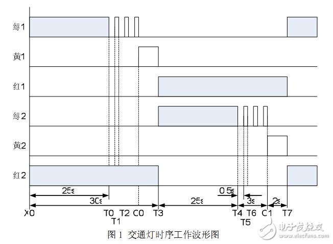
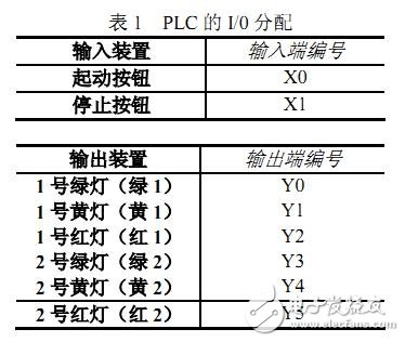
FX2N-32MR can be used as the PLC for controlling traffic lights. As can be seen from the timing diagram, the system has one input device and six output devices. Table 1 is the correspondence table of the address numbers of input devices and output devices and PLC.
The control of traffic signal lights is a typical timing control diagram. The key to the ladder diagram design is to indicate the "time point" of the state change of each light (Y0~Y5), and the precise calculation of time is realized by timer. In this example, T0~ T9 has a total of 10 timers; the number of times the light flashes should be realized by a counter. In this example, two counters will be used. The table is the instructions for the time points formed by each timer and counter.
2 Probability and method of sequential controlPLC is the product of the combination of electronic technology, computer technology and relay logic automatic control system. It is based on sequence control and supplemented by loop adjustment. It can complete functions such as logic judgment, timing, memory and arithmetic operations. PLC has the advantages of compact structure, small size, convenient operation, strong anti-interference ability, flexible and simple programming, safe and reliable work, low energy consumption, etc., which makes it quickly occupy the leading position in industrial automation control. The external wiring of PLC is simple and convenient. The program to achieve automatic control.
2.1 System ladder diagram design
Switch X0, after the selector switch is pressed, the program starts to cycle. East-west direction green 1 lights for 25s, north-south red 2 lights for 30s; T0 is green 1 lights for 25s. Timer, T0 set value K250, start timing from X0 on. When the time is up, green 1 is turned off, T1 is timed; T1, T2 are green 1 flashing 3 times, T1, T2 form oscillation, green 1 is on when T1 is on, C0 counts; C0 is the starting point of east-west yellow 1 and 2s, T2 C0 counting signal, yellow 1 is on when C0 is on; T3 is yellow 1 on for 2s timer, T3 is set to K20, T3 is set to K20, when T3 is on, red 1 and green 2 are on, red 2 is off ; T4 is a timer with red 1 on for 30s, T4 set value K300, red 1 goes out when T4 is on, and one cycle ends. T5 is a green 2 light on 25s timer, T5 set value K250, from the time T3 is turned on, the timing time to green 2 is turned off, T6 timing; T6, T7 are green 2 flashing 3 times control, T6, T7 form oscillation , Green 2 lights up when T6 is on, C1 counts; C1 is the starting point of north-south yellow 2 lights for 2s, T7 is the counting signal of C1, and yellow 2 lights up when C0 is on; T8 is yellow 2 lights for 2s timer, T8 set value When K20 and T8 are connected, yellow 2 goes out, and one cycle is over.
2.2 Sequence control method
Sequential control is based on the pre-defined sequence of the production process, under the action of each input signal, according to the internal state and time sequence, during the production process, each actuator automatically and orderly operates. The PLC designers inherited the idea of relay sequence control, provided a large number of general and special programming elements and instructions for the design of sequence control programs, and developed a sequence function diagram language for designing sequence control programs, making it a current The main method of PLC programming. Sequential control design method is also called step control design method. It is an advanced design method that is easily accepted by beginners. Experienced engineers will also improve the efficiency of design. Program debugging, modification and reading are also very convenient.
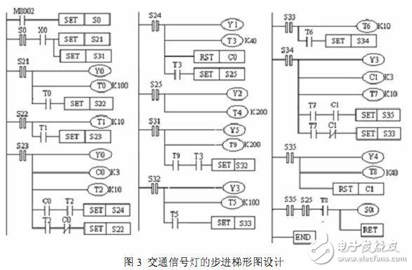
Figure 2 and Figure 3 show the sequential function diagram and step ladder diagram design of traffic lights.
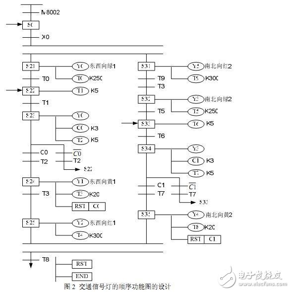
These two pictures have the following characteristics:
1) Decompose a complex task or process into several processes (states). No matter how complicated the process is, it can be divided into small processes, which is very conducive to the structured design of the program.
2) Compared with a specific process, the control task is simplified, which brings convenience to the programming of partial programs.
3) The overall program is a synthesis of partial programs. As long as the conditions for the establishment of each process, the conditions for process transition and the direction of transition are clarified, this type of graphic design can be carried out.
4) The state transition flowchart is readable and easy to understand, and can clearly reflect the whole process of process control.
State transition diagram is an important tool for state programming. The general idea of state programming is: decompose a complex control process into several working states, clarify the work content of each state (state function, transition condition and transition direction), and divide each independent state according to the general control sequence requirements Link together to form a state transition diagram, draw a ladder diagram program, and write a statement list.
2.3 Empirical Ladder Diagram Design Method
The empirical design method and the sequential control design method are appropriately compared below for selection during design. When using the empirical design method to design the ladder diagram, it is impossible to find a simple and universal design method.
Sequential control design method divides the whole program into two parts: control program and output program. Since the steps are divided according to the state of output Y, there is a very simple logical relationship between M and Y, and the design of the output program is extremely simple. And generation
No matter how complicated the control program of the auxiliary relay or status relay of the table step is, the design method is the same, and it is easy to master.
3 ConclusionThis article is a typical ladder diagram design of traffic lights at intersections. The most design practice is to propose a design theory for PLC in traffic control systems, and to propose a feasible method for PLC in complex control systems in the future. Theoretical solution. In practical applications, PLC is used to control urban traffic lights, and the control program can be modified at any time according to different road conditions to change the working hours and working conditions of each signal light. Compared with relay or logic circuit control system, PLC control system has higher reliability, flexibility and economical practicality.
The above is the PLC traffic light control system design we have listed for you. You can submit the following form to obtain more industry information we provide for you.
You can visit our website or contact us, and we will provide the latest consultation and solutions
Send Inquiry
Most Popular
lastest New
Send Inquiry
Send Inquiry

Ms. Anny
Email:
Send Inquiry Tel:86-514-84230418
Fax:86-514-84238418
Mobile Phone:+8618852753718
Email:
Address:Lingtang industry park,China,Gaoyou city, Yangzhou, Jiangsu
Related Products List
Mobile Site
Privacy statement: Your privacy is very important to Us. Our company promises not to disclose your personal information to any external company with out your explicit permission.
Fill in more information so that we can get in touch with you faster
Privacy statement: Your privacy is very important to Us. Our company promises not to disclose your personal information to any external company with out your explicit permission.